S/HDU Holdown
Product Details
The S/HDU series of holdowns combines performance with ease of installation. The predeflected geometry virtually eliminates material stretch, resulting in low deflection under load. Installation using self-drilling tapping screws into the studs reduces installation time and saves labor cost.
Material
- 118 mil (10 ga.)
Finish
- Galvanized (G90)
Installation
- Use all specified fasteners; see General Notes
- Use standard #14 self-drilling screws to fasten to studs
- Anchor bolt washer is not required
- See SB, SSTB and PAB Anchor Bolts for cast-in-place anchorage options
- See SET-3G™ and AT-XP® adhesive products for anchor bolt retrofit options
Related Literature


Product Information Table
| Model No. | Thickness (mil) | Ga. | H (in.) | Coating/Material | Packaging Qty. |
|---|---|---|---|---|---|
| S/HDU11 | 118 | 10 | 16 5/8 | Zinc Galvanized, G90 | 1 |
| S/HDU4 | 118 | 10 | 7 7/8 | Zinc Galvanized, G90 | 1 |
| S/HDU6 | 118 | 10 | 10 3/8 | Zinc Galvanized, G90 | 1 |
| S/HDU9 | 118 | 10 | 12 7/8 | Zinc Galvanized, G90 | 1 |
Load Tables
These products are available with additional corrosion protection. Additional products on this page may also be available with this option.
Contact Simpson Strong-Tie for details.
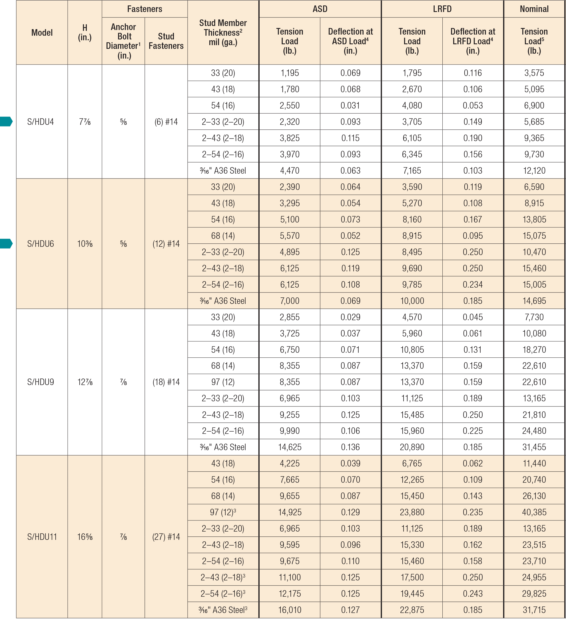
- The designer shall specify the foundation anchor material type, embedment and configuration. Some of the tabulated holdown tension loads exceed the tensile strength of typical ASTM A36 or A307 anchor bolts.
- It is acceptable to use the capacity listed for the thickest single member or back-to-back members for thicker stud members in the same configuration. Stud design by specifier.
- A heavy hex nut for the anchor bolt is required to achieve the table loads for S/HDU11.
- Deflection at ASD or LRFD is the deflection of the fastener slip, holdown deformation, and anchor rod elongation for holdowns installed up to 4" above the top of concrete when loaded to the ASD and LRFD load, respectively. Holdowns may be installed raised to 18" above the top of concrete, with no load reduction provided that additional elongation of the anchor rod is accounted for. This movement is strictly due to the holdown deformation under a static load test attached to members listed in the table above.
- The Nominal Tension Load is based on the tested average ultimate (peak) load and is provided for design under section E1 of AISI S400 that categorized the holdowns as capacity-protected components. Based on AISI S400, the nominal load shall be greater than or equal to the required strength. Per AISI S400, holdowns are Capacity Protected Components and they are not part of the designated energy-dissipating mechanism. Nominal strength to resist amplified seismic load is not required.
- See Fastening Systems for more information on Simpson Strong-Tie fasteners.
Code Reports & Compliance
Drawings
| DWG | DXF | RFA | IFC | SAT | |||
|---|---|---|---|---|---|---|---|


