×
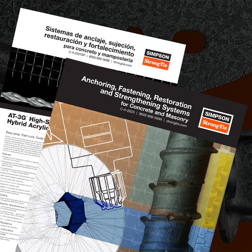
Anchoring & Fastening Systems for Concrete and Masonry
Innovative Anchor Solutions for Infrastructure, Commercial and Industrial Construction
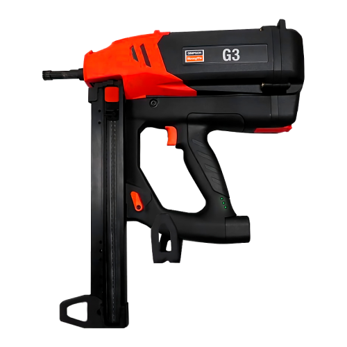
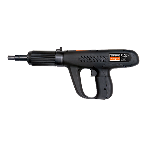
One of the core values at Simpson Strong-Tie is to help you succeed by providing innovative products, full-service engineering, field support, product testing and training, and on-time product delivery. We strive to provide innovative anchor systems solutions for infrastructure, commercial, industrial and residential projects. We offer a full array of mechanical anchors, adhesive solutions, and tools for concrete and masonry applications. Our anchor systems solutions, like all of our others, have passed the high performance and quality standards that are expected of Simpson Strong-Tie — and include the trusted level of service you’ve come to rely on.
Browse by Category
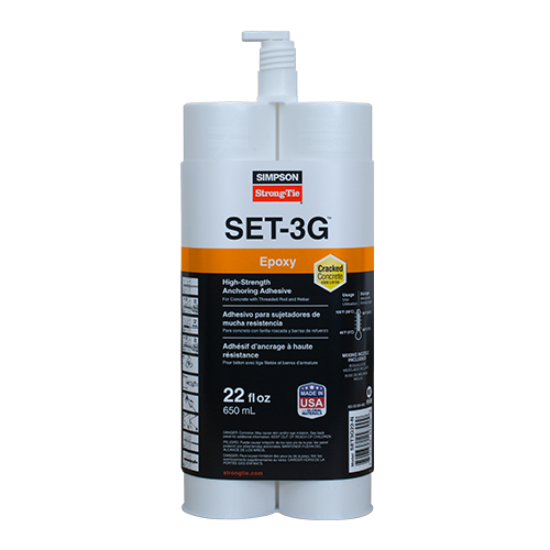
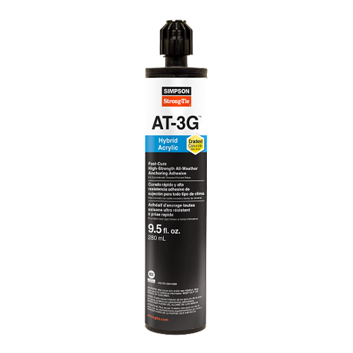
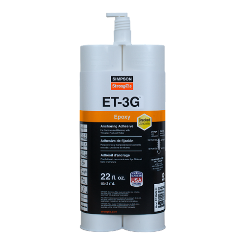
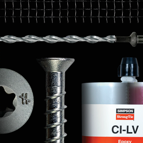
Adhesive Solutions
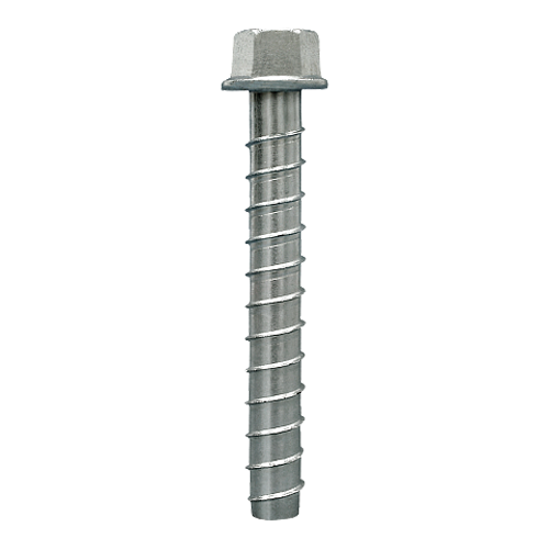
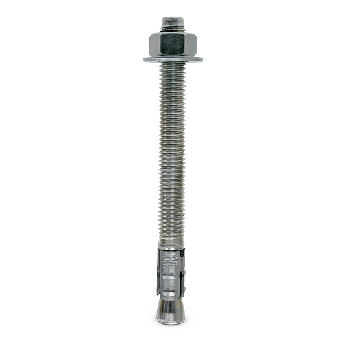
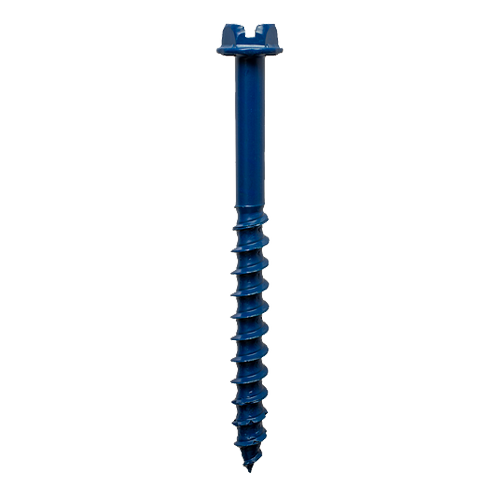
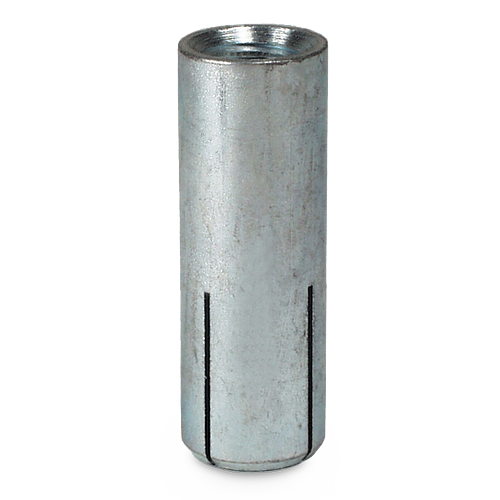
Mechanical Anchors
Software & Literature
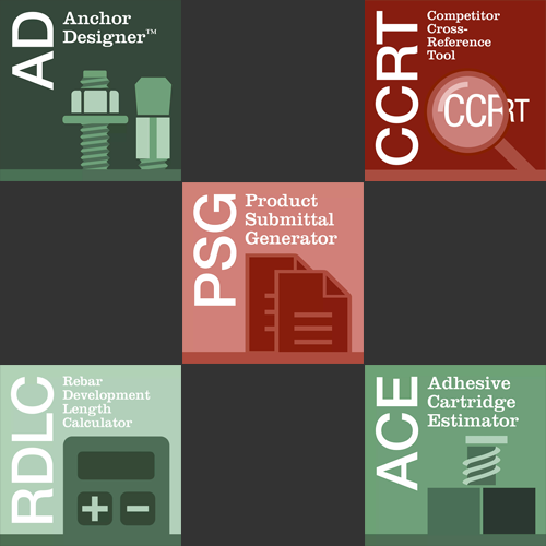
Resources
Important Information and General Notes
- Warning and General Notes for Anchoring Systems
- Anchor Selection Guide
- Material Data Safety Sheets
- Powder-Actuated Fastening — Safety Principles and Warning Signs
- Supplemental Topics for Anchors
- Allowable Stress Design (ASD) Method and Strength Design (SD) Method Information
- Suggested Specifications (2012 CSI Format) and General Notes for Anchoring Systems
- Glossary of Common Terms for Anchoring and Fastening Systems