
Wood Construction Connectors
Strength Beyond Steel
At Simpson Strong-Tie, our drive to innovate sets us apart. For 70 years, through precision engineering and rigorous testing, we have been pushing the boundaries of wood construction connector design to match your most demanding applications with the fastest, easiest and strongest products available. It’s our promise to deliver the expert knowledge and support that ensures your ability to build safer and smarter, for every job.
Contact us today to find out how we can help take your next project to the next level.
Browse by Category

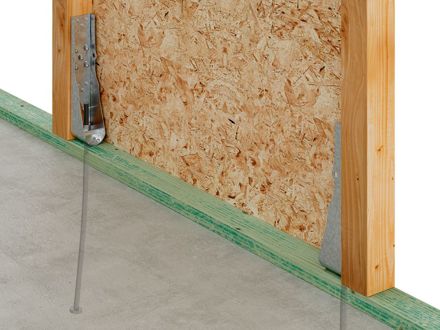
Introducing the HDUE™ holdown and SABR™ anchor bolt solution.
Together, the HDUE holdown and SABR anchor bolt provide a stronger, faster way to secure shearwall end studs to concrete foundations.
New Connectors
Our advancements in steel connectors have led to countless improvements in construction, including better ways to protect homes from earthquakes and high winds. From hangers to hurricane ties and holdowns, our broad range of connectors supply the versatility, reliability and high-performance you need to succeed.
Take a look at our latest products and find the right solution for your project.
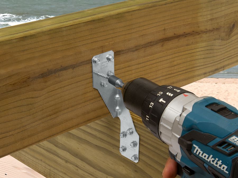
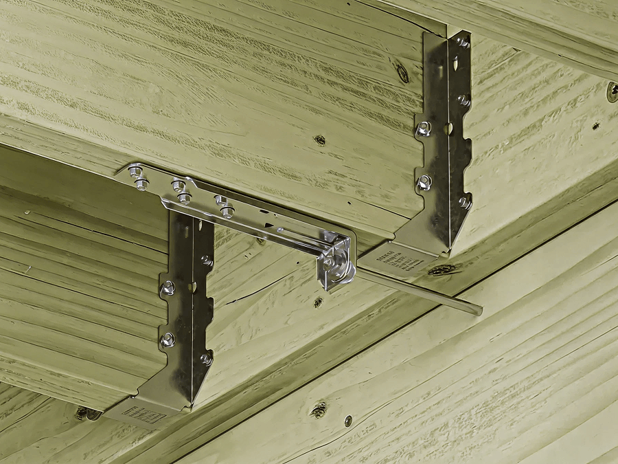
Stainless Steel Connectors
For exterior wood-to-wood or wood-based materials involving Wet Service, Elevated Service, Ocean/Water Front Service and Uncertain Environments prone to chemicals and chlorides, we offer stainless steel connectors for a variety of building applications.
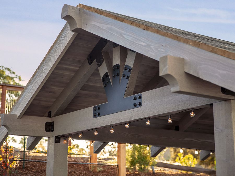
Outdoor Accents
The complete Simpson Strong-Tie Outdoor Accents® decorative hardware line featuring ornamental wood connectors and fasteners, brings both beauty and strength to outdoor living structures.
Wood Connector Solutions and Web Apps


Resources
General Notes
- General Notes for Wood Construction Connectors
- General Notes for Holdowns and Tension Ties
- General Notes for Hanger Options
- General Notes for Straps and Ties
- General Notes for Bases and Caps
- Connector Holes and Specified Fastener Types
- Post Capacities
- Hanger Options Matrix
- Hinge Connector Specifier Guide
- Strong-Drive® Connector Nail Quantities
- How We Determine Allowable Loads