×
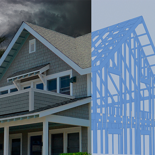
Build with the Best to Prepare for Nature’s Worst
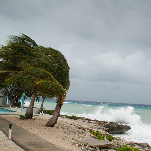
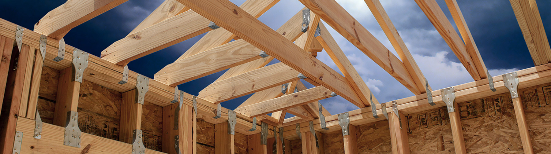
High-wind forces pose unique dangers — and thus unique challenges — to building structures. Whether you’re a specifier, builder or homeowner, our state-of-the art design solutions and comprehensive resources can help you prepare and protect structures against damage due to high-wind events. From our extensively tested products to a wealth of tools and training, we have the knowledge and the products to keep your building safe and strong.