Strong Frame® Moment Frames
We are discontinuing our Strong Frame product line and transitioning all our moment frame projects to our Yield-Link® moment connection solutions.
Strong Frame Transition Plan 2023-2024
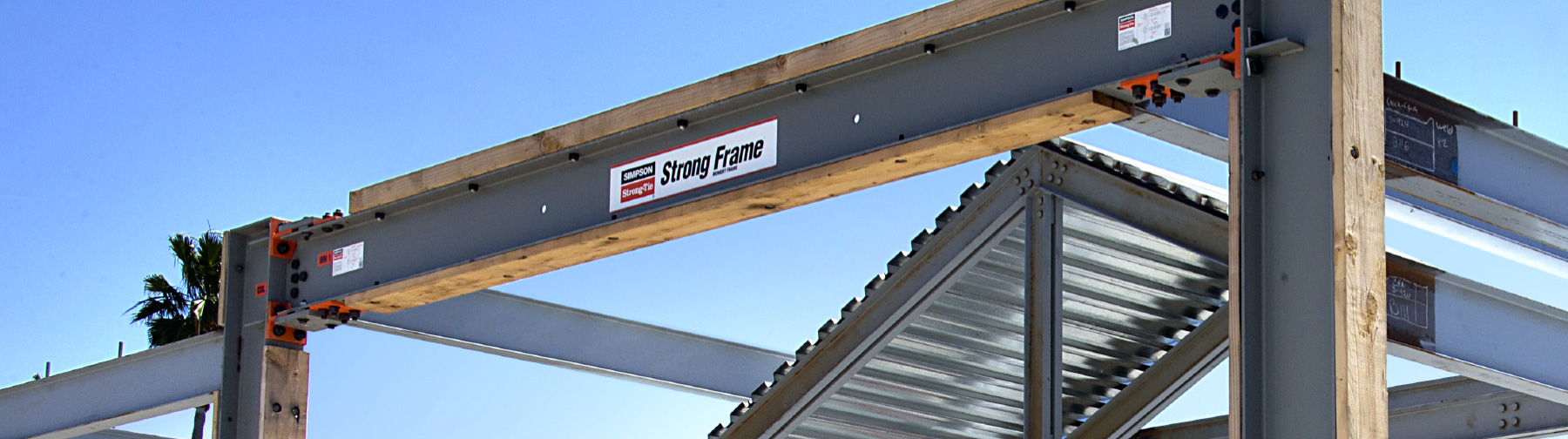
The Strong Frame moment frame using the patented Yield-Link® moment connection was launched in 2013 for the light-frame wood construction market. The Strong Frame was a prefabricated moment frame that was manufactured and shipped by Simpson Strong-Tie to the job site ready to be installed by the contractor. As demand grew for Strong Frames, so did the scale of the projects. The larger scale projects allowed Simpson Strong-Tie to work with steel fabricators to produce the beams and columns while Simpson Strong-Tie provided the Yield-Link moment connection. As a result, Simpson Strong-Tie will be discontinuing our Strong Frame product line and transitioning all our moment frame projects and design requests to our Yield-Link moment connection product line.
Designers and contractors can contact Simpson Strong-Tie to coordinate conversion of Strong Frame projects to Yield-Link projects. With a large network of steel fabricators, we can help connect customers with local fabricators for moment frames using the Yield-Link moment connection. Working with local fabricators has the benefit of additional field support and reducing lead times and cost.
Designers can continue to use our software tools to specify Yield-Link moment connection on their projects. We do not charge a design or fabrication licensing fee for our solutions. This helps reduce project schedule/cost making Yield-Link cost effective solution.