RCKW™ Kneewall Connector
Rigid Connectors
This product's information may differ depending on the category of use. You are currently viewing details related to Rigid Connectors. You can also view product information related to the category: Seismic and Hurricane Ties
Product Details
The Simpson Strong-Tie® RCKW is a heavy 171 mil (7 ga.) rigid connector that has been developed to resist overturning moment at the base of exterior kneewalls and parapets as well as interior partial-height walls or overhead ribbon window conditions. These connectors offer a unique small and large anchor-hole pattern that permits anchorage to both concrete and structural steel. Single 1/2" anchor or (2) 1/2" anchor options are available in all sizes for attaching to concrete. If load requires more capacity, a stiffener, the RCKWS can be added. The RCKWS is a heavy 171 mil (7 ga.) stiffener that nests onto the RCKW clip. The screw holes and anchor holes in the stiffener line up with those in the RCKW clip, making fastener and anchor installation a snap. The RCKW clip and RCKWS stiffener are sold separately.
Key Features
- In addition to our RCKW3 and RCKW3S with a large single bolt hole for 3 5/8" framing, we have the RCKW3D and RCKW3DS, which have two large holes for anchorage. This provides an option for more capacity in 3 5/8"-framed kneewalls.
- Anchorage legs incorporate stiffened flanges, improving overturning moment resistance.
- Large-diameter anchor holes accommodate 1/2"-diameter concrete screw anchor and wedge anchors, such as the Simpson Strong-Tie Titen HD® heavy-duty screw anchor and the Strong-Bolt® 2 wedge anchor.
- The RCKW5.5 and RCKW7.5 have three large holes for added versatility. The center hole is for a one-anchor solution at the edge or center of slab. The outer holes are for a two-anchor solution that requires higher capacities at the center of slab. In addition, two 3/8" Titen HD screw anchors have been tested in the outer holes for shallow embedment conditions like fluted deck. The RCKW3 and RCKW3S have single large holes in the center, and the RCKW3D and RCKW3DS have two large holes on the outside for increased anchorage capacity
- Additional smaller-diameter anchor holes enable attachment to structural steel with #12 self-drilling screws.
- Attachment to CMU can be achieved with Titen HD or Titen Turbo™ concrete and masonry screws.
- For the RCKWS: 171 mil (7 ga.) stiffeners are secured to the RCKW clip with screws, optimizing overturning moment resistance and stiffness.
Material
- RCKW, RCKWS, RCKWD and RCKWDS: 171 mil (7 ga.), 33 ksi
Finish
- Galvanized (G90)
Installation
- Use all specified screw fasteners. To achieve tabulated load values, use #12–14 screws according to the fastener patterns shown in the installation illustrations.
- When using the RCKWS, secure the stiffener to the clip with the specified screw fasteners. Screws must be at least 1" long and extend through the connection with a minimum of three exposed threads.
- Use all specified anchors. To achieve tabulated stiffness values, the installation torque for concrete anchors shall be at least 17 ft.-lb. or the torque requirements of the anchor, whichever is greater.
- When using the larger-diameter anchor holes, the bottom track must be predrilled or punched with a 3/4"- diameter hole.
Patent Information
- US Patent 9,938,709
Related Literature


Product Information Table
| Model No. | Thickness (mil) | Ga. | Coating/Material | Packaging Qty. |
|---|---|---|---|---|
| RCKW3D-R10 | 171 | 7 | Zinc Galvanized, G90 | 10 |
| RCKW3DS-R10 | 171 | 7 | Zinc Galvanized, G90 | 10 |
| RCKW3-R10 | 171 | 7 | Zinc Galvanized, G90 | 10 |
| RCKW3S-R10 | 171 | 7 | Zinc Galvanized, G90 | 10 |
| RCKW5.5-R10 | 171 | 7 | Zinc Galvanized, G90 | 10 |
| RCKW5.5S-R10 | 171 | 7 | Zinc Galvanized, G90 | 10 |
| RCKW7.5-R10 | 171 | 7 | Zinc Galvanized, G90 | 10 |
Load Tables
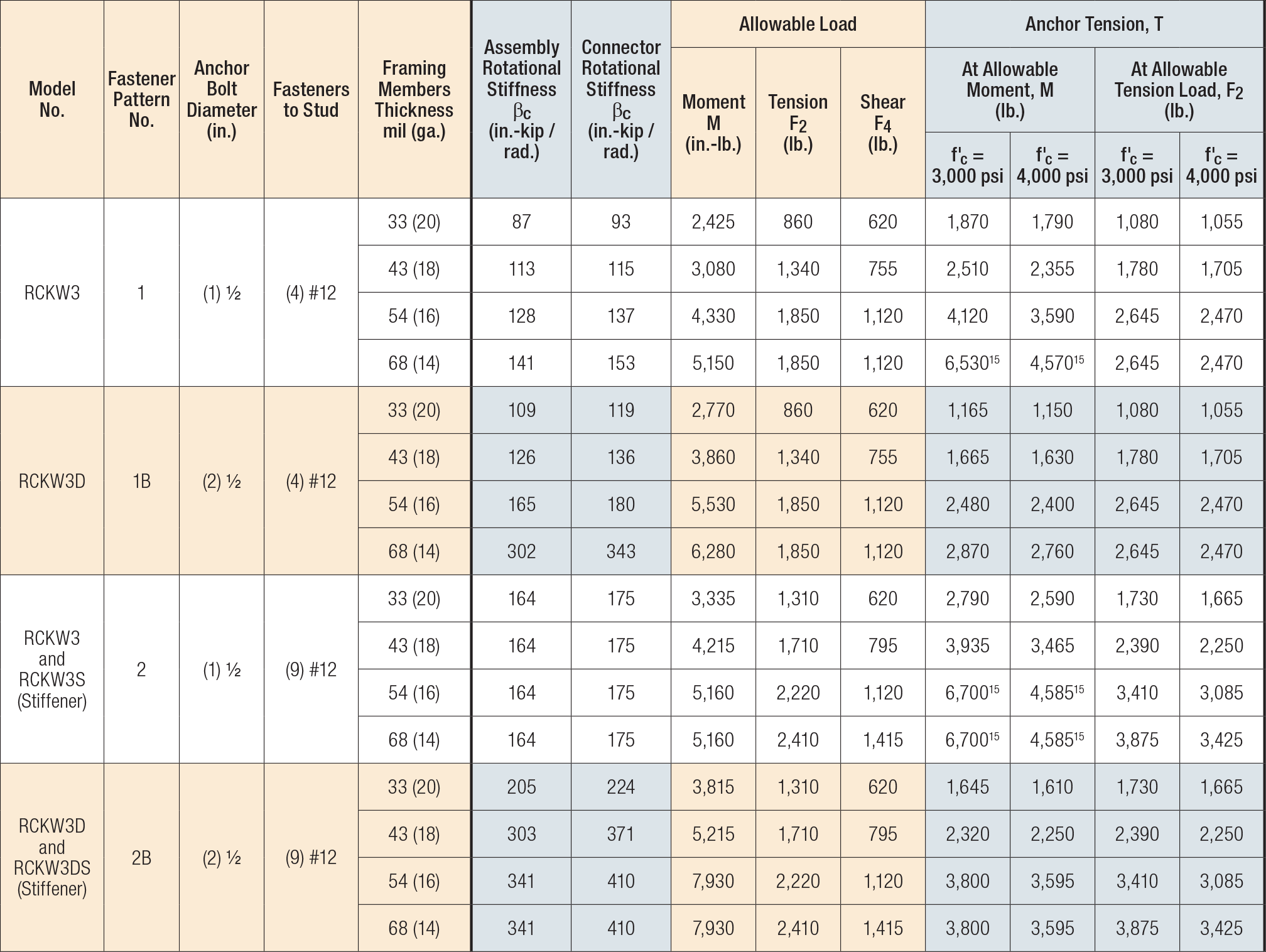
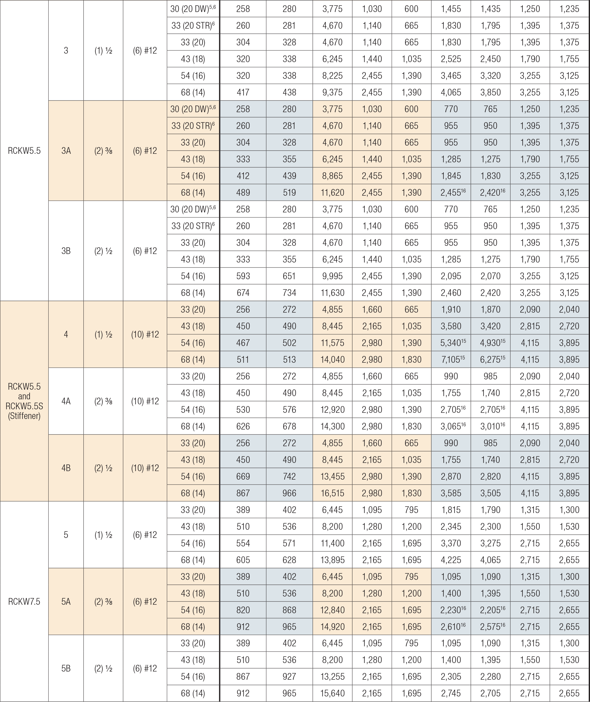
Table 1: RCKW Allowable Loads (lb.) — Concrete Applications
- For additional important information, see General Information and Notes.
- The designer is responsible for anchorage design.
- See illustrations for fastener pattern placement.
- Tabulated values are based on framing members with track and stud of the same thickness and (1) #10 screw into each stud flange unless otherwise noted.
- Tabulated values may be used for framing members with track and stud of thickness 20 mil, Fy = 57 ksi (20 EQ).
- Tabulated values are applicable for framing members with CFS track of thickness 20 mil, Fy = 57 ksi (20 EQ).
- EQ — equivalent, DW — drywall, STR — structural.
- Tabulated moment values correspond to maximum connector strength without consideration of serviceability. Designer must check out-of-plane deflections using tabulated Rotational Stiffness.
- Tabulated Assembly Rotational Stiffness is applicable for walls at 38" tall with corresponding framing member depth and thickness. Reference Example #1 on p. 123 of C-CF-2023.
- Tabulated Connector Rotational Stiffness may be used for any wall heights; the designer must consider member deflection due to bending in the stud member. Reference Example #2 on pp. 124-125 of C-CF-2023.
- Per IBC 2012 and later Table 1604.3 footnote f, wind load is permitted to be taken as 0.42 times "component and cladding loads" for deflection checks. For IBC 2009 and earlier, the factor is 0.7 instead of 0.42. Tabulated values have not been adjusted.
- Anchor tension, T, is the force in the anchor, or both anchors for two-anchor solutions, at maximum allowable, M, or maximum allowable tension, F2.
- Tabulated values for anchor tension, T, at allowable tension load, F2, are provided for total anchor tension for (1) anchor and (2) anchors. See Table 2: RCKW Allowable Anchorage Loads (lb.).
- Anchor tension is calculated using AISC Steel Design Guide 1. The 'Anchor Bolt Design' illustration (Figure B) shows the anchor tension, T, based on an applied moment, M. An illustration for the anchor tension, T, based on a vertical tension load, F2, shown in Figure C.
- Tabulated allowable tension loads for the connectors with 1/2"-diameter anchor bolts require ASTM F3125, Grade A325 or ASTM A449 high-strength bolts. For A307 Grade A bolt, anchor tension load is limited to 4,410 lb.
- Tabulated allowable tension loads for the connectors with 3/8"-diameter anchor bolts require ASTM F3125, Grade A325 or ASTM A449 high-strength bolts. For A307 Grade A bolt, anchor tension load is limited to 2,200 lb.
- Anchor tension, T, may be interpolated. See footnotes for Table 2: RCKW Allowable Anchorage Loads (lb.)
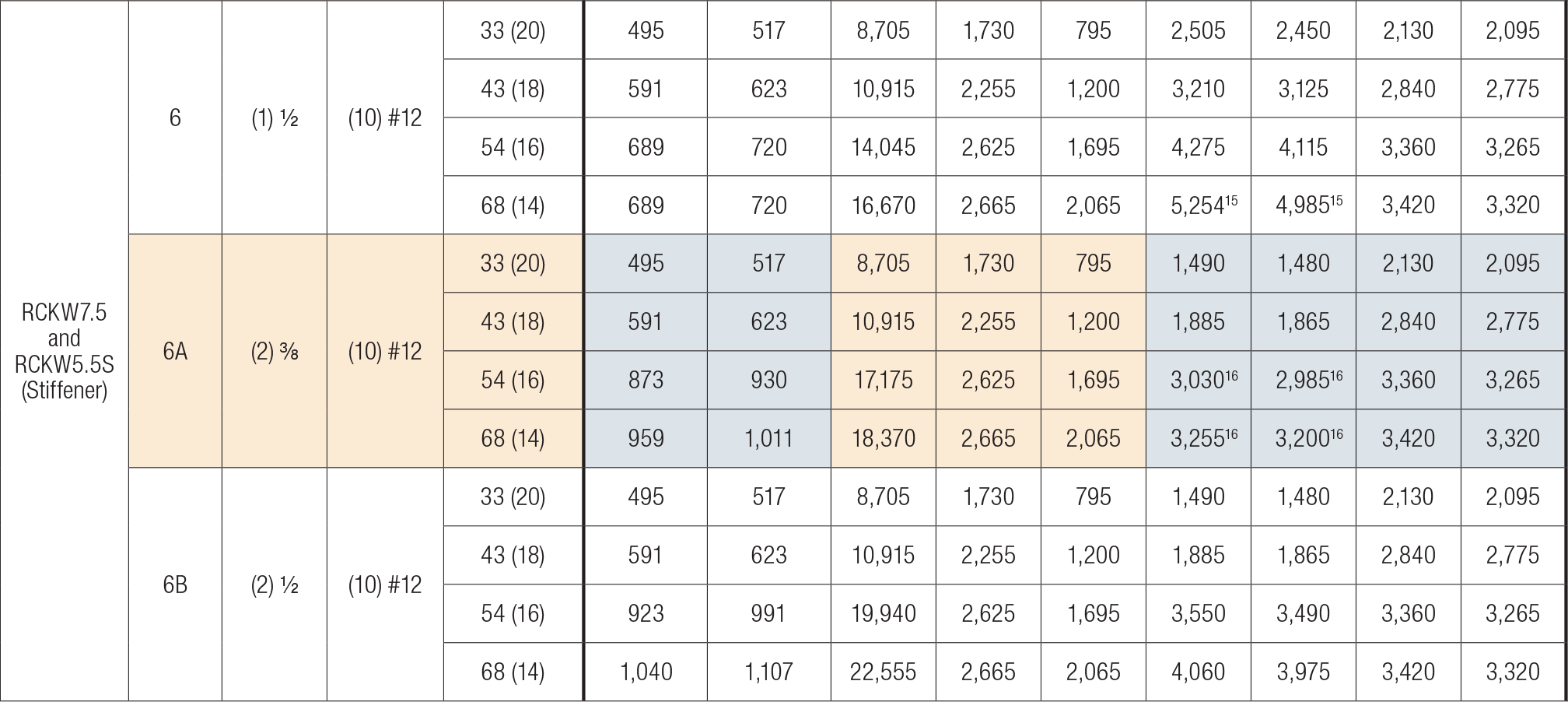
Table 2: RCKW Allowable Anchorage Loads (lb.)
- Anchor Allowable Loads have been determined using ACI 318-14 Chapter 17 anchorage calculations with the minimum concrete compressive strength, f'c, and slab thickness listed. Sand-Lightweight Concrete is abbreviated as 'SLWC', Normal Weight Concrete is abbreviated as 'NWC'.
- Load values are for anchor based on ACI 318-14, condition B, load factors from ACI 318 Section 5.3, no supplemental edge reinforcement, ψc,V = 1.0 for cracked concrete and periodic special inspection. Reference ICC-ES or IAPMO-UES evaluation reports for further information.
- Load values are based on short-term temperature range of 160°F and 180°F for SET-3G™ and AT-XP® adhesives, respectively. Long-term temperature range is assumed to be 110°F for SET-3G and AT-XP adhesives.
- Allowable Stress Design (ASD) values were determined by multiplying calculated Strength Design values by a conversion factor, Alpha (α), of 0.7 for seismic loads and 0.6 for wind loads. ASD values for other load combinations may be determined using alternate conversion factors.
- End distances are assumed as 1.5 x Min. Edge Distance in one direction and 'N/A' in the other direction. See installation in image gallery.
- Edge and end distances are assumed as 'N/A' in all directions at locations for (No Edge).
- Tabulated anchorage capacities for RCKW models shown are applied to the same model size with stiffener. For example, a value for model RCKW3 is equivalent to model RCKW3 and RCKW3S.
- Tabulated allowable ASD loads for Wind and Seismic in SDC A and B are based on using wind conversion factors and may be increased by 1.17 for seismic SDC A and B only.
- Allowable loads have been divided by an Omega (Ω) seismic factor of 2.5 for brittle failure as required by ACI 318-14 Chapter 17, unless steel failure governs.
- Tabulated capacities are based on maximum allowable anchorage loads only. The capacity of the connection system shall be the minimum of the tabulated value and the RCKW allowable load value listed in Table 1: RCKW Allowable Loads (lb.) — Concrete Applications.
- Tabulated loads in Table 2 are based on f'c = 4,000 psi. For f'c = 3,000 psi, use an adjustment factor of 0.86 for the blue shaded values and 1.0 for all other values.
- For anchor subjected to both tension and shear loads, it shall be designed to satisfy following:
— For Na / Nal ≤ 0.2, the full allowable load in shear is permitted.
— For Va / Val ≤ 0.2, the full allowable load in tension is permitted.
— For all other cases: Na / Nal + Va / Val ≤ 1.2. where:
Na = Applied ASD tension load
Nal = Allowable tension load from Table 2
Va = Applied ASD shear load
Val = Allowable shear load from Table 2.
Table 3: RCKW Allowable Loads — Steel Applications with Anchorage
- For additional important information, see General Information and Notes.
- Designer is responsible for structural steel design.
- See illustrations for fastener patterns.
- Tabulated values are based on framing members with track and stud of the same thickness and #10 screws into each stud flange.
- Tabulated moment values correspond to the maximum connector strength without consideration of serviceability. Designer must check out-of-plane deflections using tabulated Rotational Stiffness.
- Tabulated Assembly Rotational Stiffness is for walls at 38" tall.
- The tabulated Connector Rotational Stiffness is for any wall heights. The designer must consider member deflection due to bending in the stud.
- Per IBC 2015 Table 1604.3 footnote f, wind load is permitted to be taken as 0.42 times "component and cladding loads" for deflection checks. For IBC 2009 and earlier, the factor is 0.7 instead of 0.42.
Code Reports & Compliance
Drawings
| DWG | DXF | RFA | IFC | SAT | |||
|---|---|---|---|---|---|---|---|


