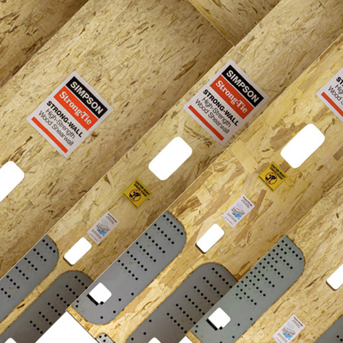
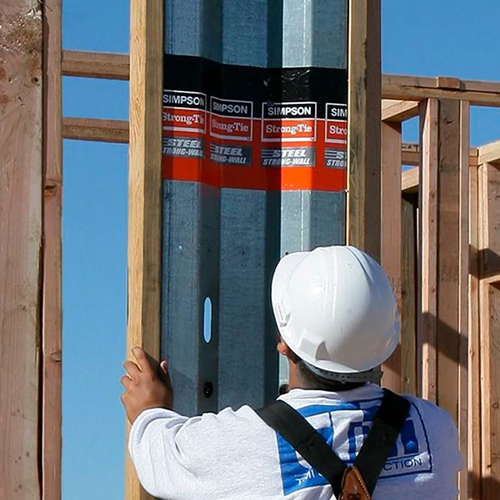
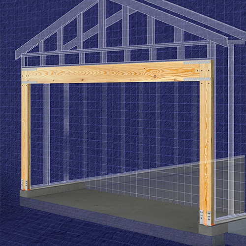
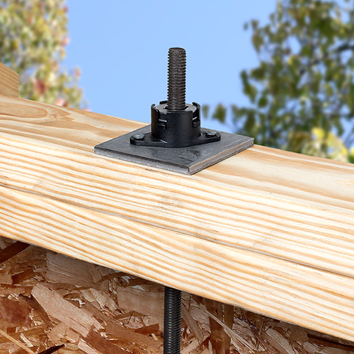
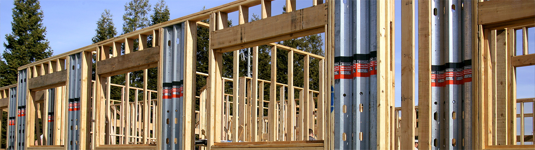
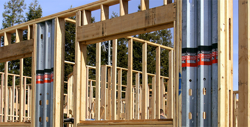
The Strong-Wall® Wood Shearwall garage portal system provides higher shear capacity with reduced concrete anchorage requirements. Portal walls may be used in single- or double-portal applications and shall be installed with a minimum 3 ⅛ single- or multiple-ply header depending upon loading and span requirements.
Model No. | H Curb (in.) | Rough Opening Height (in.) |
---|---|---|
WSW12x7 WSW18x7 WSW24x7 |
5½ 6 |
6'-11½ 1 7'-0 1 |
WSW12x7.5 WSW18x7.5 WSW24x7.5 |
0 | 7'-1½ |
WSW12x8 WSW18x8 WSW24x8 |
5½ 6 |
8'-2¾2 8'-3¼2 |
Model No. | Contents |
---|---|
WSW-PK | 4 (10 Gauge) WSW-PS Straps |
A portal frame under lateral loads causes the portal header to experience internal stresses in addition to those created by the primary loads (live, dead and snow). These additional stresses are called induced forces and must be considered when designing portal headers. To account for the induced forces from lateral loads, a concentrated end moment equal to the top-of-panel moment must be placed at the end of the beam that is connected to the WSW panel. For WSW12 and WSW18 panels, the moment induced into the portal header must be taken as 20% and 10%, respectively, of the total lateral moment. The total lateral moment is calculated as the design shear times the panel height. For headers with typical residential uniform loads, the induced moment and shear forces from a portal-frame system do not control the design. This is due to the 1.60 load duration factor (CD) used in design and the induced stresses from wind and seismic loads.
The lateral and vertical loads shown on page 17 for portal frames assume that the header size falls within the portal-frame parameters listed in the table.
Header Design Parameter | Allowable Range |
---|---|
Width | 3 ⅛" – 5 ½" |
Depth | 9¼" – 18" |
Clear Span | 8' – 18' 6" |
K | 90 lb./in. – 4,000 lb./in. |
These alternative garage-front options may be used for applications when the Strong-Wall® Wood Shearwall is installed at the full height (option 1) or without the additional Portal-Frame Kit (option 2), when higher capacity or reduced concrete anchorage is not needed. Refer to the Standard Application on Concrete Foundations on pages 12-13 for product data and allowable load values.
For Garage Wall Option 2, the Designer shall design for: