Strong-Drive® TB WOOD-TO-STEEL Screw
Product Details
Key Features
- Flat head with nibs for easy countersinking
- #3 square drive (driver bit in each box; replacement bit model BIT3S-2-R2; use BIT3SU-2-RC3 for mechanically galvanized — N2000®)
- #4 drill point with wings
- Installation Guidelines: Maximum recommended thickness up to 1/4"
Applications
- Wood to hot-rolled steel (maximum recommended thicknesses: 1/4")
Warning
- Industry studies show that hardened fasteners can experience performance problems in wet or corrosive environments. Accordingly, use this product in dry, interior and noncorrosive environments only.
Related Links
- Fastening Systems Technical and Installation Notes
- Strong-Drive TB Wood-to-Steel Screw also available collated for the Quik Drive® system
Catalog Pages
- Fastener Product Information: C-F-2023 (Fastening Systems), page 115
- Fastener Technical Data and Loads: C-F-2023TECHSUP, page 212
Related Literature


Product Information Table
| Model No. | Coating/Material | Screw Size | Length (in.) | Head Diameter (in.) | Shank Diameter (in.) | Drive Type | Head Type | Thread Type | TPI | Max. Grip Length (in.) | Point Type | Point Size | Approx. Count per Lb. | Packaging Qty. |
|---|---|---|---|---|---|---|---|---|---|---|---|---|---|---|
|
Footnotes
|
||||||||||||||
| TBG1260R1500 | N2000® Mechanically Galvanized | #12 | 2 3/8 | 0.390 | 0.175 | #3 Square | Flat Head | Tapping Threads | 14 | 1.65 | Drill Point with Wings | 4 | 61 | 1500 |
| TBP1245R2000 | Black Phosphate Coating | #12 | 1 3/4 | 0.390 | 0.175 | #3 Square | Flat Head | Tapping Threads | 14 | 1.06 | Drill Point with Wings | 4 | 86 | 2000 |
| TBP1245R50 | Black Phosphate Coating | #12 | 1 3/4 | 0.390 | 0.175 | #3 Square | Flat Head | Tapping Threads | 14 | 1.06 | Drill Point with Wings | 4 | 86 | 50 |
| TBP1460R1000 | Black Phosphate Coating | #14 | 2 3/8 | 0.460 | 0.198 | #3 Square | Flat Head | Tapping Threads | 14 | 1.65 | Drill Point with Wings | 4 | 43 | 1000 |
| TBP1460R50 | Black Phosphate Coating | #14 | 2 3/8 | 0.460 | 0.198 | #3 Square | Flat Head | Tapping Threads | 14 | 1.65 | Drill Point with Wings | 4 | 43 | 50 |
| TBP1475R1000 | Black Phosphate Coating | #14 | 3 | 0.460 | 0.198 | #3 Square | Flat Head | Tapping Threads | 14 | 2.24 | Drill Point with Wings | 4 | 39 | 1000 |
| TBP1475R50 | Black Phosphate Coating | #14 | 3 | 0.460 | 0.198 | #3 Square | Flat Head | Tapping Threads | 14 | 2.24 | Drill Point with Wings | 4 | 39 | 50 |
Product Information Table
| Model No. | Length (in.) | Max. Grip Length (in.) | Screw Size | Drive Type | Head Diameter (in.) | Head Type | Thread Type | TPI | Shank Diameter (in.) | Point Size | Point Type | Coating/Material | Appx Count Per Lb | Packaging Quantity | UPC |
|---|---|---|---|---|---|---|---|---|---|---|---|---|---|---|---|
| TBP1245R2000 | 1 3/4 | 1.06 | #12 | #3 Square | 0.39 | Flat Head | Tapping Threads | 14 | 0.175 | 4 | Drill Point with Wings | Black-Phosphate Coating | 86 | 2000 | 707392876335 |
| TBP1245R50 | 1 3/4 | 1.06 | #12 | #3 Square | 0.39 | Flat Head | Tapping Threads | 14 | 0.175 | 4 | Drill Point with Wings | Black-Phosphate Coating | 86 | 50 | 707392504559 |
| TBG1260R1500 | 2 3/8 | 1.65 | #12 | #3 Square | 0.39 | Flat Head | Tapping Threads | 14 | 0.175 | 4 | Drill Point with Wings | N2000® Mechanically Galvanized | 61 | 1500 | 707392553267 |
| TBP1460R1000 | 2 3/8 | 1.65 | #14 | #3 Square | 0.46 | Flat Head | Tapping Threads | 14 | 0.196 | 4 | Drill Point with Wings | Black-Phosphate Coating | 43 | 1000 | 707392520917 |
| TBP1460R50 | 2 3/8 | 1.65 | #14 | #3 Square | 0.46 | Flat Head | Tapping Threads | 14 | 0.196 | 4 | Drill Point with Wings | Black-Phosphate Coating | 43 | 50 | 707392116158 |
| TBP1475R1000 | 3 | 2.24 | #14 | #3 Square | 0.46 | Flat Head | Tapping Threads | 14 | 0.196 | 4 | Drill Point with Wings | Black-Phosphate Coating | 39 | 1000 | 707392503767 |
| TBP1475R50 | 3 | 2.24 | #14 | #3 Square | 0.46 | Flat Head | Tapping Threads | 14 | 0.196 | 4 | Drill Point with Wings | Black-Phosphate Coating | 39 | 50 | 707392817550 |
| * Grip length includes side member, steel thickness, air gap (if any) and allowance for three threads protuding through the steel. | |||||||||||||||
Load Tables
TB — Allowable Loads — DF and SP Lumber Attachment to Steel (Steel Members 16 ga.– 5/16" Thick)
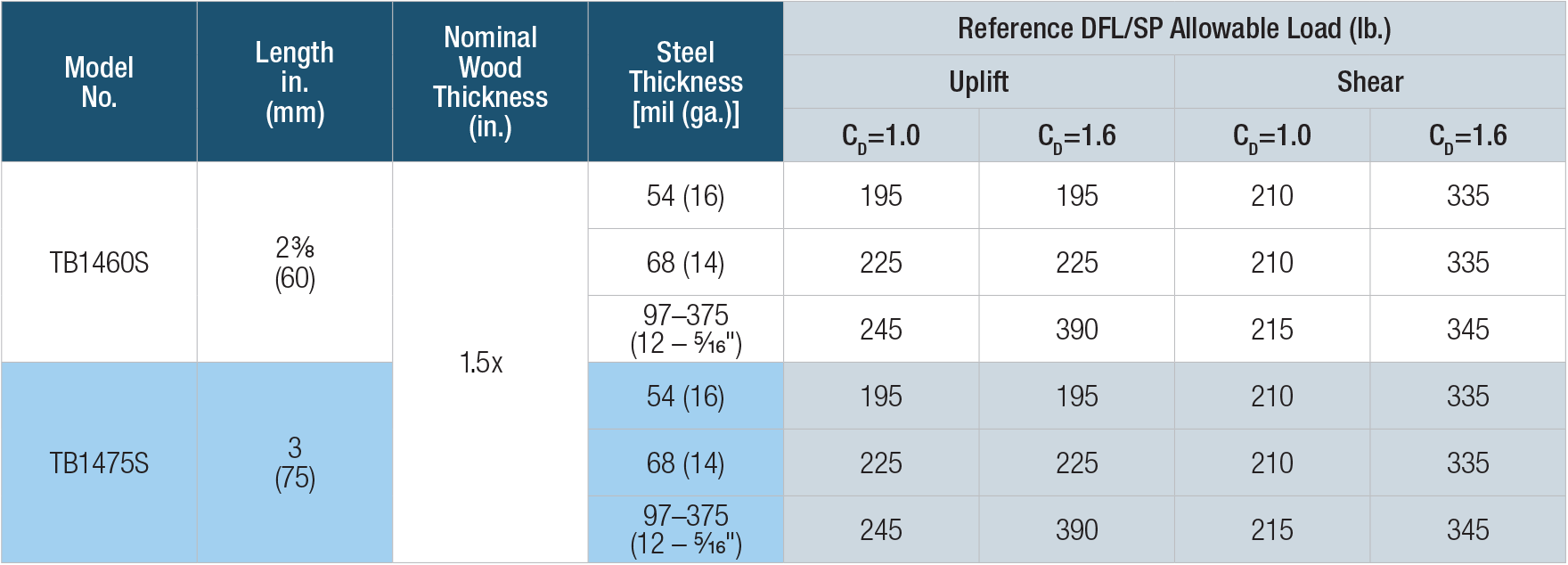
- For use with structural steel members up to 5/16" thick or cold-formed steel members 54 mil (16 ga.) or thicker.
- Minimum steel strength Fu = 45 ksi.
- Standard product available in a black phosphate coating. Mechanically galvanized (N2000) coating available for additional corrosion protection.
- Reference allowable loads are based on tests using 2x (1.5 in.) thick wood members.
- Use increased allowable loads (CD = 1.6) only when resisting wind or seismic forces. Values must be multiplied by all applicable adjustment factors per the NDS.
- Minimum fastener spacing requirements to achieve allowable loads: 4" end distance, 1.5" edge distance, 1.5" between staggered rows, 3" between non-staggered rows, and 4" between fasteners in a row.


Code Reports & Compliance
Drawings
| DWG | DXF | RFA | IFC | SAT | |||
|---|---|---|---|---|---|---|---|


