×
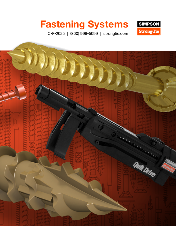
Quik Drive Auto-Feed Screw Driving Solutions
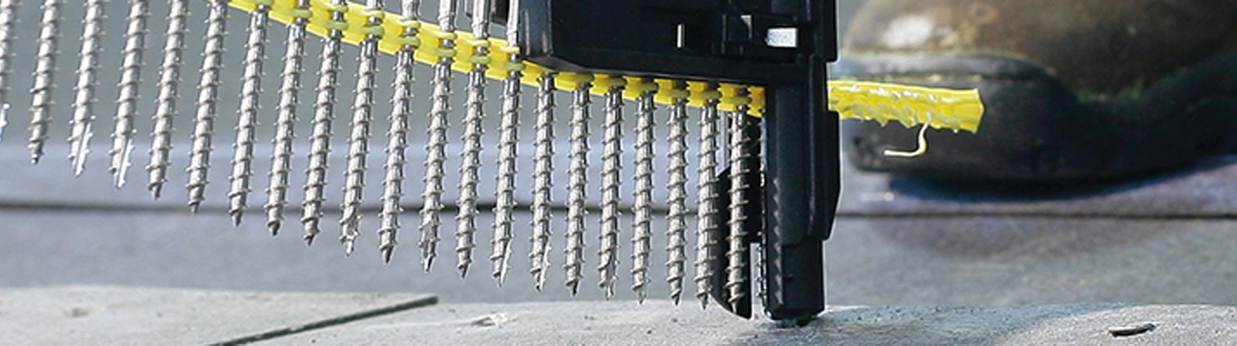
Quik Drive® Auto-Feed Systems increase productivity while providing superior fastener performance
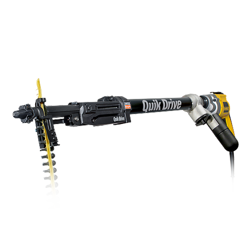
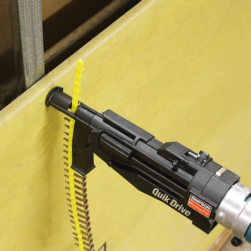
Fastening has never been as fast or as cost-effective. Collated-screw fastening tools are replacing traditional nail guns for their speed, reliability and power. Quik Drive auto-feed screw driving systems are easy to use, durable and designed for a wide variety of fastening applications. Featuring quick-loading screw strips, precise countersink adjustment and a patented auto-advance mechanism, Quik Drive tools save time and expense on jobsites every day.
Browse Systems & Attachments
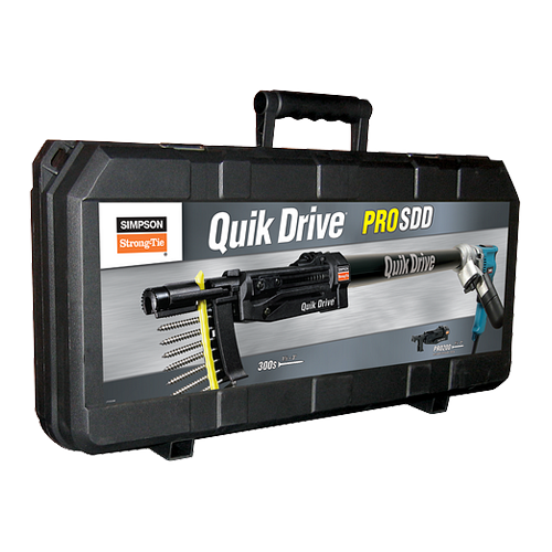
Quik Drive Systems
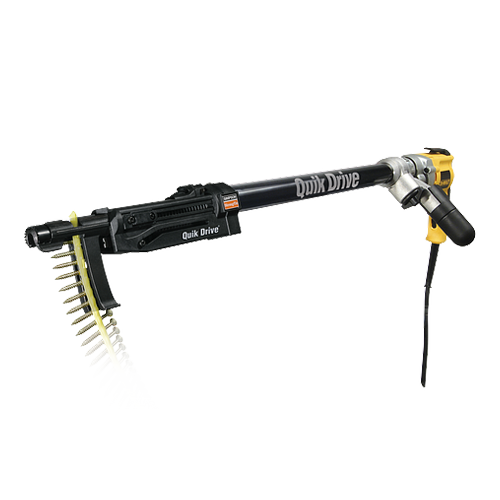
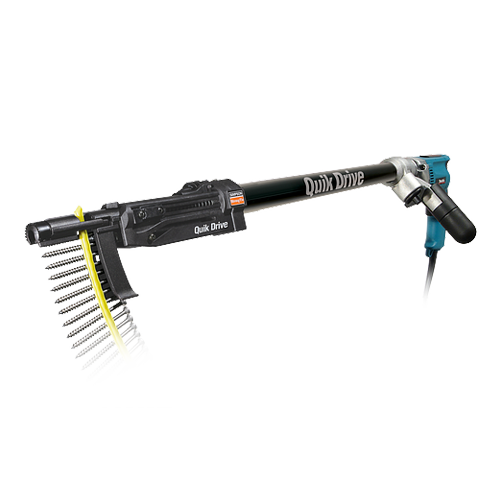
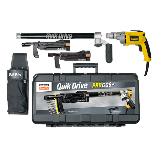
Quik Drive Combo Systems
Quik Drive Videos
Quik Drive Videos
- Quik Drive vs Pneumatic Fasteners
- Quik Drive for Subfloor Fastening
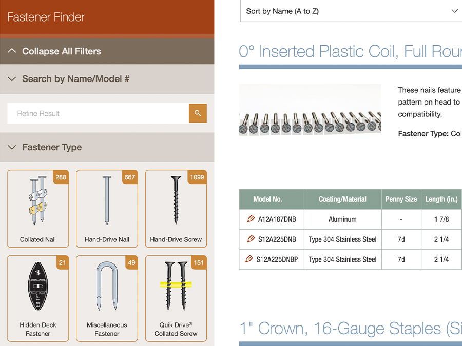
Fastener Finder
Quickly search our wide array of fasteners to find exactly what you need. Search by multiple criteria, such as application, type and model number. Explore our extensive product line in seconds.
Resources
General Notes
- Warning and General Notes for Fastening Systems
- Fastener Overview: Nails
- Fastener Overview: Screw Features
- How Self-Drilling Screws Work
- Custom-Order Nails
- Composite-Decking Color Cross-Reference
- Connectors Approved for Use with the Strong-Drive® SD Connector screw
- Fastener Tool Compatibility Matrix
- Application / Fastener / Tool Matrix
- Contact Fastening Systems